Bulan: Juli 2023

Mechanical Installation Systems

Mechanical Installation Systems

Mechanical Installation Systems – Mechanical Installation is the whole of the projects that are designed to increase the living standards and comfort in the construction works and constitute the interior of the building. Mechanical engineering is the branch of engineering.


Mechanical installation services can be listed as follows.


  • – Solar Power Installation
  • – Heating Systems
  • – Laundry and Kitchen Facilities
  • – Plumbing
  • – Natural Gas Installation
  • – Air Conditioning Installation
  • – Ventilation Installation
  • – Scientific examination
  • – Fire Installation
  • – Elevator Installation
  • – Compressed Air Installation
  • – Medical Gas Installation
  • – Steam, Condends, Hot Water and Hot Oil Installation
  • – Mechanical Automation
  • – Pool Facilities


Construction, construction, mechanical engineering, heating, cooling, ventilation and fire extinguishing systems. Mechanical installation, mechanical engineer and technical draftsmen prepare.


Mechanical installation is one of the four main project departments in the construction sector: static, architectural, electrical and mechanical.


In recent times, electromechanical electrical installation projects have become almost two working together with almost the foundation. Mechanical installation projects are prepared by mechanical engineers and technical painters. In these projects, which determine the mechanical infrastructure of buildings, industrial facilities, it is stated how the building’s heating, cooling, ventilation, fire prevention system will be and the types and powers of these devices and where the clean water and sewage lines of the building will pass.

WHAT ARE MECHANICAL INSTALLATION SYSTEMS?

Mechanical installation; This standard covers all components of the building, which are designed to increase living standards and comfort in construction, construction and industrial plant works. Therefore, it is important that each system is compatible with each other and works as a support for each other and establish the full quality.

Read More : Mavericksystemscorp.com

Mechanical Installation Systems

  • • Comfortable conditions
  • • Functionality
  • • Reliability
  • • Robustness and Long Life
  • • Compliance with advanced technology
  • • Low costs for initial investment
  • • Ease of application
  • • Ease of installation, repair, maintenance
  • • Ease of Use
  • • Expandability
  • • Water and Energy saving
  • • Environmental sensitivity
  • • After-sales installation, effectiveness of service support
  • • Sustainability of brand and product


Mechanical Installation Systems consists of 7 parts.

  1. 1. Heating system: It covers the parts that allow the building to heat up. Heating boilers or other heating equipment also includes radiators, fan-coils, convectors.
  2. 2. Cooling-Air conditioning system: This system covers the cooling of the structure in hot times. Air conditioner and so on. and Fan coil, air conditioners.
  3. 3. Ventilation system: It keeps the air in the building fresh and clean and allows the dirty air to be ejected. The ventilation system includes air handling units and fans.
  4. 4. Clean water system: Purified Water is called clean water. Water tanks are also water treatment and water softening systems. It covers domestic and potable water systems.
  5. 5. Wastewater system: Provides the safe and comfortable transportation of waste water to the exterior of the building. The building is about sewage and water costs.
  6. 6. Hot water system: It provides the production of hot water required for cleaning, washing or needs. Natural gas includes hot water production systems such as coal and diesel oil.
  7. 7. Fire-extinguishing system: In case of fire in a short time to intervene systems.

GRANT TERMINOLOGY

GRANT TERMINOLOGY

GRANT TERMINOLOGY – The grants community is diverse, and so is the terminology we use to talk about roles and aspects of the grants lifecycle. Here is a glossary of grant terms based on the Grant Policies and Grants.gov functionality.

Agency Specific Data Sets
Data that an agency collects in addition to data on any of the SF-424 series forms.
Applicant
Any user registered with an applicant account type. See also Individual Applicant and Organization Applicant
Application
The specific set of forms, documents, and attachments that comprise an applicant’s submission to a federal grant opportunity.
Application Package Template
One or more forms and documents which can be reused for multiple opportunity-specific application packages.
Authorized Organization Representative (AOR)
See Standard AOR and Expanded AOR.
Award
Financial assistance that provides support or stimulation to accomplish a public purpose. Awards include grants and other agreements in the form of money or property in lieu of money, by the federal government to an eligible recipient. The term does not include: technical assistance, which provides services instead of money; other assistance in the form of loans, loan guarantees, interest subsidies, or insurance; direct payments of any kind to individuals; and contracts which are required to be entered into and administered under federal procurement laws and regulations.

Budget
The financial plan for the project or program that the Federal awarding agency or pass-through entity approves during the Federal award process or in subsequent amendments to the Federal award. It may include the Federal and non-Federal share or only the Federal share, as determined by the Federal awarding agency or pass-through entity.

Cage Code
A five-character code which identifies companies doing, or planning to do business with the federal government and is assigned through SAM.
Catalog of Federal Domestic Assistance (CFDA) number
The number assigned to a Federal program in the CFDA.
CFDA program title
The title of the program under which the Federal award was funded in the CFDA.
Close Date
The deadline designated by the grant-making agency designated for submission of a particular grant application. Also see Grace Period
Closeout
The process by which the Federal awarding agency or pass-through entity determines that all applicable administrative actions and all required work of the Federal award have been completed and takes actions as described in § 200.343 Closeout of the OMB Uniform Grants Guidance.
Competition ID
A grantor selected ID that allows further distinction of the funding opportunity number which allows applications with the same funding opportunity number to be assigned unique identifiers.
Congressional District
One of a fixed number of districts into which a state is divided, each district electing one member to the national House of Representatives. Review the How to Find Your Congressional District for the SF-424 Form blog post for more information.
Continuation Grant
An extension or renewal of existing program funding for one or more additional budget period(s) that would otherwise expire. Continuation grants are typically available to existing recipients of discretionary, multi-year projects; however, new applicants may be considered.
Receipt of a continuation grant is usually based on availability of funds, project performance, and compliance with progress and financial reporting requirements. Applications for continuation may compete with other continuation requests submitted to the awarding agency.

Read More : Mavericksystemscorp.com

GRANT TERMINOLOGY

Contract
A legal instrument by which a non-Federal entity purchases property or services needed to carry out the project or program under a Federal award. The term as used in the OMB Uniform Grants Guidance does not include a legal instrument, even if the non-Federal entity considers it a contract, when the substance of the transaction meets the definition of a Federal award or subaward (see § 200.92 Subaward of the OMB Uniform Grant Guidance).
Contractor
An entity that receives a contract as defined in § 200.22 Contract of the OMB Uniform Grant Guidance.
Cooperative Agreement
A legal instrument of financial assistance between a Federal awarding agency or pass-through entity and a non-Federal entity that, consistent with 31 U.S.C. 6302–6305:
  1. Is used to enter into a relationship the principal purpose of which is to transfer anything of value from the Federal awarding agency or pass-through entity to the non-Federal entity to carry out a public purpose authorized by a law of the United States (see 31 U.S.C. 6101(3)); and not to acquire property or services for the Federal government or pass-through entity’s direct benefit or use;
  2. Is distinguished from a grant in that it provides for substantial involvement between the Federal awarding agency or pass-through entity and the non-Federal entity in carrying out the activity contemplated by the Federal award.
  3. The term does not include: (1) A cooperative research and development agreement as defined in 15 U.S.C. 3710a; or (2) An agreement that provides only: (i) Direct United States Government cash assistance to an individual; (ii) A subsidy; (iii) A loan; (iv) A loan guarantee; or (v) Insurance.
Cost Sharing or Matching
The portion of project costs not paid by Federal funds (unless otherwise authorized by Federal statute). See also §200.306 Cost sharing or matching of the OMB Uniform Grant Guidance.

Data Universal Numbering System (DUNS) Number
The decommissioned nine-digit number established and assigned by Dun and Bradstreet, Inc. (D&B) to uniquely identify entities. This number is no longer used by the Federal Government. The Office of Management and Budget (OMB) has directed federal agencies/systems to transition to the UEI (SAM) no later than April 4, 2022.
Date of Completion
The date on which all work under an award is completed or the date on the award document, or any supplement or amendment thereto, on which awarding agency sponsorship ends.
Discretionary Grant
A grant (or cooperative agreement) for which the federal awarding agency generally may select the recipient from among all eligible recipients, may decide to make or not make an award based on the programmatic, technical, or scientific content of an application, and can decide the amount of funding to be awarded. Review the What Is a Discretionary Grant? blog post for more information.
Download
Transferring data (usually a file) from another computer to the computer you are using.

E-Business Point of Contact (EBiz POC)
A user registered as an organization applicant who is responsible for the administration and management of grant activities for his or her organization. The EBiz POC is likely to be an organization’s chief financial officer or authorizing official. The EBiz POC authorizes representatives of their organization to apply on behalf of the organization (see Standard AOR and Expanded AOR). There can only be one EBiz POC per DUNS Number.
Earmark
Earmarks are grants that are appropriated by Congress prior to a peer review. The term “earmark” is a reference to the Congressional Record where the awards are written into legislation specifically with the grant applicant’s name, activity, and dollar amounts.
Expanded Authorized Organization Representative (AOR)
An AOR is a member of your organization authorized by the EBiz POC to submit applications in Grants.gov on behalf of the organization. An applicant user with the Expanded AOR role is authorized to submit any applications on behalf of the organization and has privileges that allow the user to modify organization-level settings in Grants.gov.

Blow Molding Troubleshooting Guide Top 5 Problems

Blow Molding Troubleshooting Guide – Top 5 Problems

Blow Molding Troubleshooting Guide – Top 5 Problems – Extrusion Blow Molding is a popular process for the production of HDPE chemical drums, edible oil jerry cans, beverage, chemical or pharmaceutical bottles, and more. Such popularity comes from being the most economical and highest production output forming process of plastic products that are not only durable, but very high quality. However, there is a chance of encountering some problems during this process, so when it comes to blow molding defects, it is extremely important that you learn to identify their origin and know how to handle each of them.

This blow molding troubleshooting guide will therefore introduce you to the Top 6 Common Defects and Problems of HDPE Extrusion Blow Molding, their possible causes, and solutions and recommendations which can help you obtain the best plastic products possible.

Top 5 Problems and Solutions

Becoming familiarized with blow molding defects should always be a priority. This way, when production problems arise, coming up with an efficient solution will not take too long and overall plant productivity will be kept. Therefore, this leaves no doubt that having a proactive approach to blow molding troubleshooting is necessary to prevent delays and maintain a company’s overall performance.

Blow molding troubleshooting includes a variety of defects including the following:

1.  Leakage

Leakage from HDPE bottles can be caused by many reasons, it can be due to tear in the bottle’s wall, poor welding of the molten plastic in areas such as the bottom, side or top handles; it can also be caused by the melted resin being contaminated by dirt or impurities coming from recycled material, which can lead to the product’s walls not being leakproof.

For plastic products with a narrow neck (such as bottles, jerry cans and narrow mouth drums) the source of the leakage can be at the top surface of the neck and might be a little harder to detect. When designing the tooling for your product, the blow molding manufacturer must make sure the blow pin nozzle and the mold are the perfect match, depending on the parison wall thickness, the gap between these two should be narrow enough to let the blow pin push the material inside the mold so the plastic can fill the space between the mold and the blow pin, hence making the top of the neck flat (avoiding leakage when sealing the container). If this gap is too big, the material will not be pushed inwards to fill the space and the top surface of the neck will not be flat, thus, causing leakage.

2. Rocker Bottoms

Why are rocker bottoms caused in bottles? Unstable or rocker bottoms of blow molded bottles is a problem usually caused by insufficient cooling of the blown bottle before removing it from its mold. If this is the case, try increasing the water flow of your cooling system. If there is still no result, you can also check the blow molding machine’s cooling channels for any blockage and clean them. Sometimes, the problem can be caused by excessive thickness of the parison in the flasher area at the bottom, this causes the mold to not fully close at this point and the material not touching the mold completely as it is supposed to; thus, make sure the parison thickness at this area is adequate to allow the mold to fully close.

Additionally, rocker bottoms can also be originated by poor air exhaust from the product’s neck after the blowing cycle has finished and before the mold opens; as when the product is being formed, there is air being blown at a constant pressure pushing the Parison walls against the mold, so when this process finishes, the blow pin nozzle should slightly retract and allow the extra pressure out, otherwise this pressure will most likely expand the product at the bottom, hence resulting in an unstable bottle.

3. Tearing of Welding Line at Pinch-off (or Deflashing)

Tearing of a container when deflashing the flasher material can happen and especially at the welding lines of the product (such as handle areas and the product’s bottom), a very common cause of this issue is the mold close slow speed. What does this mean exactly? To catch the parison inside, the clamping unit must close the blow mold in two steps: 1st mold close (fast speed) and 2nd mold close (slow speed), the purpose of the 2nd mold close with slow speed is to push the material inwards the mold in order to form strong welding lines, and thus, avoid tearing at these areas when removing the scrap material. So, if your bottle, drum or jerry can is having this problem, try reducing the speed of the mold slow close.

Read More : Mavericksystemscorp.com

Blow Molding Troubleshooting Guide Top 5 Problems

If after reducing the mold slow close speed the problem persists, then it might be that the parison thickness is too thin at the handle area of the jerry can or that the bottom flasher area is not enough to form a strong welding line, therefore, try increasing the thickness profile at these points in the parison so that when the mold closes, there is sufficient material to support the welding.

If the tearing keeps happening after implementing these two solutions, then the problem might come from a poor cooling system design of the mold.

4. Surface wall defects

From almost unnoticeable defects like tiny black spots, to larger ones like horizontal ring-like lines, vertical streaking lines, wall bubbles, and rough, rippled or “orange peel” like surfaces, these can all affect your bottles and appear due to many different reasons.

Black spots

Black spots can be caused by foreign matter or old resin (which has already degraded) inside the extruder die head that contaminated the melt and resulted in different colored spots on your jerry can or bottle. Sometimes, the foreign matter or old resin might be stuck inside the die bushing and causes a distortion or vertical line in the extruded parison, thus marking streaking lines in the product; the solution to this is to find where in the die head the contamination is and clean it thoroughly.

Wall bubbles

As for wall bubbles, these are caused by moisture or water particles condensed in the cold resin due to warm and high humidity climates. To avoid this, you can install a hopper dryer or try to keep the resin warm to evaporate the condensed water before it goes into the extruder hopper; also make sure cooling water flow in the extruder feed opening is not so high.

Horizontal ring-like line

When a horizontal ring-like line is formed around your drum or jerry can, it means the parison thickness difference between two consecutive points is too large, hence, the parison thickness controller will move the die or die mandrel too fast, resulting in a ring-like line showing on your product. To prevent this, gradually increase/decrease the thickness between the profile points, also keep the thickness of the first and last profile points the same or very close.

Rippled surface or orange peel

A rough surface that seems rippled or like orange peel, is caused by the parison wall coming into contact with the cold mold surface two times intermittently instead of just once, therefore, prematurely solidifying the wall before it is blown and then stretching it a second time, which does not allow the parison wall to be smoothed out. This situation can happen especially with oval shaped jerry cans and bottles because the parison is too narrow, so the pre-blow is set high in order to expand it and get an oval shape-like parison before the cycle blow. To solve this, try using a bigger die mouth so you can reduce the pre-blow, the oval shape needed for the bottle will be formed with the cutting and sealing unit of the blow molding machine.

5. Uneven Radial Wall Thickness Distribution

An even wall thickness distribution of your jerry can, bottle or drum´s wall is very important to avoid excessive shrinkage of the product and overall bad quality. How does this happen? A product with an uneven radial thickness will have a thinner side that will be cooled down faster than the one with wider thickness, therefore requiring a longer cooling time otherwise the bottle will shrink too much.

To solve this, try aligning the die mandrel(pin) and the die until the extruded parison looks straight. Because parisons with bigger diameters are easier to control than narrower ones, you can also try to increase the die mouth diameter and reduce the pre-blow of the parison as well.

Laser Alignment, Alignment Lasers or Aligning Lasers – What’s the Difference?

Laser Alignment, Alignment Lasers or Aligning Lasers – What’s the Difference?

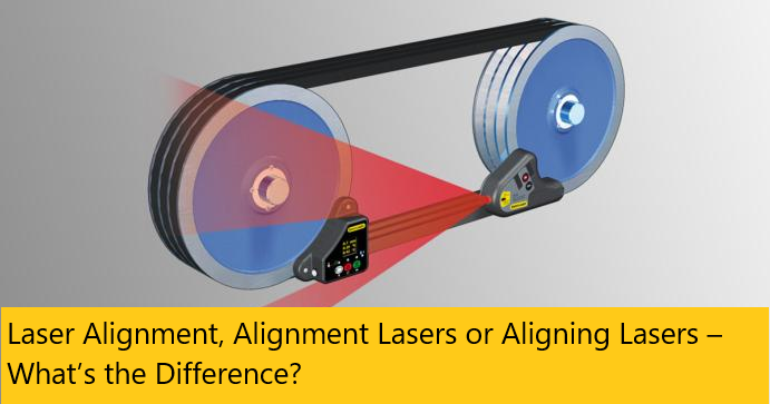
Laser Alignment, Alignment Lasers or Aligning Lasers – What’s the Difference? – Here at OASIS, we often receive requests for “laser alignment” services. However, this term can apply to several similar, but distinct solutions. In this post, we provide a brief overview of the various tools and technologies that can fall under the category of laser alignment. In future posts, we will delve further into laser alignment tools and describe the applications where each solution excels.

In our field of industrial precision alignment, laser alignment is a generic term used to describe the process of aligning machines using lasers. This term is much like the one used to describe machinery alignment performed using optical instruments, often called optical alignment. Laser alignment can be performed using alignment lasers or other portable coordinate measuring machines such as laser trackers. Laser trackers use laser technology to measure 3-dimensional coordinates quickly and with a high degree of accuracy. The alignment data gathered can be converted to geometrical points, planes, spheres or cylinders using a 3D metrology software solution. These features can then be referenced to defined datum for position, form, parallelism, perpendicularity and more. In the hands of skilled metrology engineers, portable 3D metrology tools are an innovative solution for the laser alignment of industrial machines.

Read More : Mavericksystemscorp.com

Laser Alignment, Alignment Lasers or Aligning Lasers – What’s the Difference?

Alignment lasers are specialized laser instruments specifically designed to perform industrial alignment tasks. There are many brands of alignment laser systems for all types of industrial applications including shaft alignment, and belt and pulley alignment just to name a few. Typically line or point lasers can be used for planar, rectilinear or perpendicular alignments of machine components. Alignment lasers are most often sold loaded with the programs required to perform their various capabilities. Alignment lasers do not however, provide true 3D coordinates or points, but rather provide the relative alignment of their components (emitter and receiver). Learn more about the causes of machine alignment.

The process of aligning lasers can also fall into the category of laser alignment. In this case, the intended meaning is the act of making alignment adjustments to specialized laser equipment or positioning lasers within an industrial process. Larger equipment or modular laser systems require a certain level of alignment in order to function as intended.

This post covers only a small part of the world of laser alignment. Please check back for more on the various tools, technologies and applications that can fall under the category of “Laser Alignment”. If you would like to discuss your equipment alignment needs and would like a site visit to your facility, please contact the OASIS Service Center nearest you.

Following the roll forming road map

Following the roll forming road map

Following the roll forming road map – Roll forming specialist David Rostocil doesn’t believe in “black magic.” People say that the best roll formers have to gain a “feel” for the process, but Rostocil doesn’t think of it that way.

“You have to take the black art out of it,” he said. “We don’t want to just have a feel for it. We want to gauge the rolls. We want to know what we have.”

That’s the idea behind Rostocil’s forming seminars. As senior technical performance specialist at Roll-Kraft, he has held numerous events, organized by his Ohio-based employer as well as by organizations like the Fabricators & Manufacturers Association International®.

A 40-year industry veteran, Rostocil spent 20 of those years at a custom roll form facility. As he tells the story, he didn’t learn the craft by gaining a “feel” for the machine. He learned by listening to his mentors, the “old engineers” who taught him the ropes and talked about specifics, like what to do and what to avoid to operate an efficient rolling mill, setup after setup.

The Destination and Vehicle

“Sometimes the people who run these machines are seen as not very technical,” Rostocil said. “Sometimes they don’t have drawings. But how can operators know where to go if they don’t have drawings? They may need to be trained or attend a seminar, but it doesn’t take long with the proper training. They learn very fast.”

In effect, the print gives the operator the destination. It identifies the dimensions, material grade, material thickness, radii, and the key control passes. Every set of tooling usually has at least two key control passes, and depending on the severity of the formed section, the operator could have multiple passes that need the proper amount of overform in each to accommodate for material springback.

The setup chart (see Figure 1) is the operator’s vehicle that gets him to the destination. Setup charts should include not only the basics—number of passes, rolls and shim specs, flange gauging points, as well as inboard and outboard spacer dimensions—but also operator notes describing setup intricacies as well as lessons learned from previous runs.

For instance, say a job requires side-roll stands. Before the first pass, the setup sheet might include an explanation, “Mount side-roll stand before the first pass; use edging rolls to keep return legs even.” Additional notes might include something like, “Excessive pressure on passes 9-12 will cause leg heights to become short.”

As Rostocil explained, it’s difficult to give too much information on the setup chart. The more complete the chart is, the smoother an operator’s roll forming road trip will be.

The Road Map

If the print is the destination, and the setup chart represents the vehicle, a documented standard operating procedure is the road map.

The procedure should involve setting the rolls on the machine, gauging the rolls to ensure the distance between them matches the thickness specified on the setup chart, and checking the side clearances and roll alignment without material in the rolls.

(To troubleshoot one pass that is out of alignment, a technician should pull the tooling off and gauge it on a surface plate, Rostocil said. The machine itself may be perfectly aligned; the problem may lie with the tooling. Measuring both the machine and the tooling can help pinpoint the cause of the misalignment. For more on alignment, see the Roll Forming Maintenance Tips sidebar.)

Check the roll spacing. The operator inspects all the rolls to make sure the space between the upper and lower tools mirrors what’s shown on the part print. To do this, the operator places a piece of white paper behind a roll set, then places a mirror in front of the rolls and tilts it 45 degrees. This gives him a good view of the space between the rolls, which should match the part profile on the print (see Figure 2). If it does not, the operator needs to adjust the tooling accordingly, by using shims to align the rolls.

Alternatively, an operator can just crack the nut on the shaft and insert a horseshoe, or split, shim without taking the tooling off the machine. If the operator does this, he will need to double-check the alignment using a feeler gauge. “But watch out,” Rostocil said. “Those horseshoe shims can work their way out at high speeds, and you can lose your alignment anyhow.”

Check the entry table height. Next comes what Rostocil said is a step many operators forget: using a straight edge to make sure the entry table is at the proper height, aligned with the entry rolls (see Figure 3). “Many assume the entry table is always going to be perpendicular and parallel going into the entry rolls. If the table is not perfectly in line with the tooling, the material will skew and twist at the end of the machine. Many times operators focus on the rolls near the end, when the problem really starts at the entry table.”

Read More : Mavericksystemscorp.com
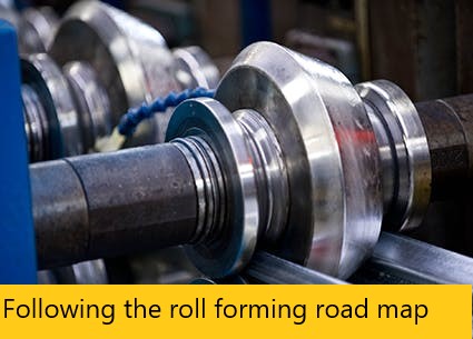
Following the roll forming road map

Set the side-pass stand height and center the side rolls. Similarly, if the job’s tooling set uses side rolls—which are mounted on a vertical axis and located between passes to help maintain the profile shape—an operator should check the stand height with a dial indicator.

To center the side rolls, the operator can use a straight edge to measure from the flat surface on the roll form machine, from the pass just before or after the side-pass stand. The distance on both sides of the roll should be the same.

Measure the material thickness. To find the most efficient route, an operator needs to know exactly where he’s starting out, and this is where the material comes into play. An operator should measure the actual thickness of the coil material that will be formed. If the setup chart and print says 16-gauge material, an operator may just set up the material for 0.060 in. Yet the actual material may be a little thicker or thinner.

“You need to make sure the tooling will accept the thickness of material that’s coming into the machine,” Rostocil said.

“If you don’t know exactly what material thickness is being formed into the machine, how do you know where you’re going?”

When setting the rolls with the material, the operator should make sure the feeler gauge has a snug fit between the upper and lower shafts (see Figure 4). “It should be a little snug,” Rostocil said, “and it should feel the same on both the inboard and outboard sides of the machine. You need to make sure you have the proper clearances for the material and for the radii being formed, and make sure everything is set.”

Feed, jog, and adjust. Even on a brand-new machine, the roll stands’ gearbox components (bearings, housing and adjustment nuts, etc.) shift upward once material feeds into the rolls. To compensate for the bearing slop and other movements, an operator inserts a feeler gauge between the top and bottom rolls to reset the roll position to the proper gap. Where to put the feeler gauge depends on the tool profile, but usually the operator places the gauge to ensure the roll remains as parallel as possible on the shaft.

Still, the worst thing an operator can do here is to adjust quickly down “hard” on the gauge until the material feed slows. “This is where you get the squeeze-out,” Rostocil said. “Squeeze-out” occurs when the top and bottom rolls, gapped too close together, squeeze and distort the material, causing twist, bow, camber, and other issues during production. Instead, operators jog the material 1 or 2 in. to allow material to seat in the rolls, then readjust and jog again as necessary. Then it’s on to the next roll.

“For newbies, this can take quite a while, maybe up to 20 minutes per stand,” said Rostocil. “But once you get accustomed to it, you can adjust the roll fairly quickly.”

Run test pieces, measure, then add the straightener and cutoff. The number and length of test pieces depend on the job, but regardless of the application, operators need to measure the profile, compare it to the print, make the appropriate adjustments, then document them in the setup chart.

Once the piece meets specifications, operators then can add the straightener as well as a cutoff system. As Rostocil explained, the straightener is there to account for material and process variation, and it shouldn’t need to straighten the section coming off the mill significantly. In fact, ideally, the section should emerge from the mill as straight as possible. “Otherwise, you might have trouble running a straight profile during production.”

Benefits of Documentation

Material quality matters in any metal forming process, and this of course includes roll forming. But as Rostocil explained, it’s not the operator’s job to complain about the material. “It’s his job to help document the process and make it work.”

This includes documenting material thickness variation, the adjustments those variations require, and even the time those adjustments take. It’s one reason that measuring material thickness periodically throughout the run is so important. He can then share that documentation with supervisors and purchasing personnel.

“I worked at a roll form company for 20 years, and spending a few cents more for better material gave us more than twice the production,” Rostocil said.

Similar thinking goes for tooling choices and the number of stations (passes) on a mill. A roll form operation may try to “make it work” with fewer-than-optimal roll stands, sometimes adding some side rolls to ensure proper forming. All this adds to the setup time, though, and can make the process unpredictable. Documenting all this may help make the case for more roll stations and a better tooling setup.

If the operator records where variation occurs—from poor material or a suboptimal tooling setup—and includes all the subsequent adjustments that variation causes, he ultimately can help the company make better decisions. And those decisions should be based not on some special black magic or a feel for the process, but actual process data that shows what’s happening at the roll forming mill—and why.

Roll Forming Maintenance Tips

To ensure the machine stays in good working order, technicians should perform a comprehensive integrity check and alignment. If an operator performs basic preventive maintenance tasks, such as applying grease and tightening bearing nuts, technicians shouldn’t have to check alignment very often, sometimes just once a year. But as always, maintenance frequency depends on the application.

Roll form machine maintenance includes ensuring bearings on the stands are in good working order, are preloaded properly, and give the proper “float” to accept the shafts. A tech may also inspect the inside diameter of the shafts using a telescoping or boring gauge and inspect the outside diameter with a micrometer to ensure it’s within tolerance (usually within -0.001 in. per 1 in. of the shaft OD).

For drive stands, where the inboard stand incorporates the transmission, the technician will inspect the bearing blocks and tighten and adjust by machining them or using shims to ensure the assembly has a tight fit and the slide can move the top shaft up and down with precision.

The top shoulder also needs to be lined up with the bottom shoulder, often by using sizing rolls of equal width as a “fixture,” slid along the shaft against the top and bottom shoulders. This gives the tech more points of contact when using a straight edge.

Once the tools and spacers are on the machine, the technician can place a straight edge on both sides of the rolls to ensure the top and bottom shafts are parallel. If spacers are too narrow for a straight edge, a tech may insert a drill rod against the rolls to check for parallelism.

A technician also checks for shaft parallelism by placing a feeler block between the shafts, being sure alignment is the same on both the inboard and outboard sides.
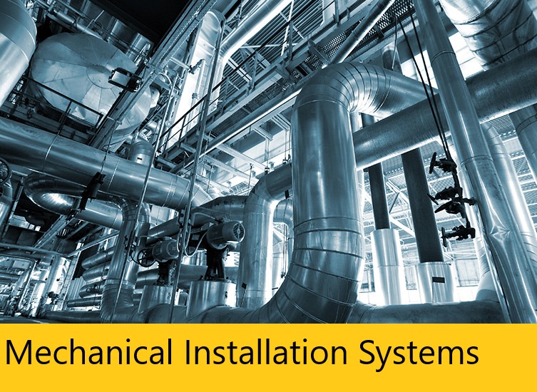
Best Laser Cutters for Small Businesses in 2023

Best Laser Cutters for Small Businesses in 2023

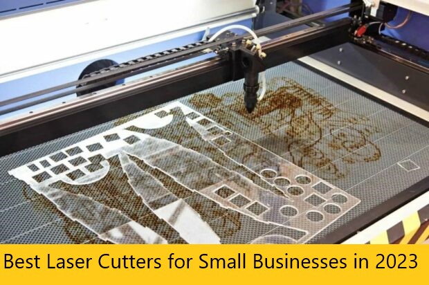
Best Laser Cutters for Small Businesses in 2023 – Small businesses frequently use laser cutters for a range of tasks; they’re great for jewelry, signage, and prototyping. Factors such as size, power, and price are important considerations for a small business owner who is looking to buy a laser cutter. To help you make an educated choice, we’ve assembled the following list of the top 12 laser cutters for small businesses in 2023:

1. xTool M1

The xTool M1 has distinguished itself as the first desktop hybrid laser and blade-cutting machine. It doubles as a laser cutting and engraving machine as well as a blade cutting machine. Depending on the materials you wish to cut or engrave, you can choose between two models: the 5W and 10W versions. The xTool M1 can be applied to a wide variety of materials including metal, glass, and wood. For materials such as vinyl, its laser may not be the best option because burnt vinyl releases toxic fumes. This is where the blade becomes valuable. In one pass, the xTool M1 is powerful enough to cut through 8 mm of basswood. Some hardware specifications for this hybrid machine include a carving precision of 0.01 mm, a laser spot of 0.08×0.08 mm, and a work area of 385×300 mm. The xTool M1 has a laser cutting speed and a blade cutting speed of 30,000 mm/min and 10,000 mm/min respectively. A 10W costs about $999 while the 5W model costs around $899.

2. Glowforge® Plus 3D Laser Printer

The Glowforge® Plus 3D laser device contains a 40W CO2 laser that utilizes a focused beam of light to cut or engrave many types of materials including: acrylic, wood, anodized aluminum, fabric, cardboard, leather, and glass. It is an upgraded version of the Glowforge® Basic and is highly valuable in the academic space because of its versatility. However, it should be operated in a well-ventilated environment or run in conjunction with the Glowforge® air filter. The Glowforge® Plus provides a precision of up to 0.025 mm and retails for $4,995. This desktop device was designed in-house and is suitable for both home and office use. It can cut through 12.7 mm of hardwood and has a build area of 292×508 mm. The cutting speed is 24,000 mm/min.

3. Orion Motor Tech Laser Cutter

The 50W Orion Motor Tech laser comes in handy when cutting and engraving non-metallic materials such as: acrylic, rubber, cardboard, bamboo, and fabric. This device is known for its high-resolution standard optics and high-precision stepper motor. These hardware features give it the ability to engrave or cut materials with relative precision. It boasts a cutting speed of up to 23,927 mm/min. When the object to be engraved is cylindrical (such as a plastic cup), the cylinder rotary attachment makes it possible for an operator to engrave around the circumference. The Orion Motor Tech, which sells for $1,799, has a build area of 305×508 mm. For safety purposes, it also comes with an emergency stop button.

4. Epilog Zing 24

The Zing 24 is intended for high-quality engraving and cutting on a variety of materials, including: glass, leather, acrylic, and wood. With a 610×305 mm engraving area, the Epilog Zing 24 is appropriate for a range of projects. The Zing 24 is available in 30W, 40W, 50W, and 60W laser power options. The cost of the device ranges from approximately $11,000-$16,000. It is renowned for both its flexible capabilities and high-quality output. Some of its special features include air assist, a red dot pointer, and autofocus. The device is highly accurate and can engrave or cut intricate designs with precision. Though it is a versatile cutting and engraving machine, it is not suitable for metal-cutting applications.

5. xTool D1 Pro

xTool D1 Pro is a diode laser device. It is an upgraded version of the xTool D1 and is available in 5W, 10W, and 20W laser power options. The laser spot (0.08×0.1 mm) in the 20W model is finer than that on the 5W and 10W modules which come with compressed laser spots of 0.08×0.06 mm. It is available at a price range of $629.99-1,099.99. The xTool D1 Pro machine’s high-resolution capability makes it possible to achieve deep cuts and engravings on a variety of materials. For instance, the 20W model can cut 8 mm acrylic or 10 mm basswood in a single pass. The 5W and 20W models have work areas of 430×390 mm while the 10W model has a work area of 430×400 mm. The maximum speed of the xTool D1 Pro is 24,000 mm/min.

Read More : Mavericksystemscorp.com

Best Laser Cutters for Small Businesses in 2023

6.  Spirit GLS X252

The Spirit GLS LaserPro X252 is an industrial-grade laser engraving and cutting device. It has a work area of 635×458 mm and a resolution of 125-1000 DPI. With a maximum power of 100 watts, the laser is perfect for engraving and cutting a wide range of materials, including: ceramic, composite, anodized metal, leather, wood, acrylic, and plastic. Very high positional accuracy lets this machine make precise and intricate cuts and engravings. The smartPIN auto-focus feature of the GLS LaserPro X252 is one of its unique features. This feature makes it simple and quick to focus on materials of various thicknesses. It also enables plug-and-play functionality. The Spirit GLS X252 costs approximately $9,399.62. Also included among its features is the smart center technology which makes it easier to find the center points of irregular shapes.

7. Morphon 130W Laser Cutter

The powerful and effective Morphon 130W Laser Cutter is made for professionals. With a 130-watt laser, it can pierce a variety of materials, including: metal, leather, wood, and acrylic. This machine’s cutting speed is also impressive, reaching a top speed of 30,000 mm/min to enable quick and accurate cuts. High accuracy is one of this device’s most notable characteristics. The Morphon 130W Laser Cutter is an excellent choice for those looking for a high-quality laser cut. It is reasonably priced and has a work area that measures 1397×889 mm. One potential drawback of the Morphon 130W Laser Cutter is its size; it has a relatively large footprint compared to other laser cutters of similar power and capability.

8. SUNCOO K-40 Laser Cutter

The SUNCOO K-40 Laser Cutter is a multifunctional tool that enables users to cut and engrave a variety of materials. There are only a few minor differences between it and the laser model known as Morphon K-40. With a build area of 305×203 mm, the K-40’s 40W CO2 laser can easily cut through materials like leather, acrylic, and wood. The SUNCOO K-40 has incredible speed in addition to power. Users can complete projects quickly and effectively thanks to its cutting speed of up to 21,030 mm/min. The SUNCOO K-40 is also affordable — at $1,929, it’s priced very competitively compared to other laser cutters with similar capabilities.

9. Bobs CNC Evolution 3 Laser Cutter

BobsCNC offers DIY kits that enable the BobsCNC router to serve also as a cutter and engraver. The appropriate mountable laser will depend on whether yours is an E-series, Evolution series, or KL series CNC device. To create a hybrid or all-in-one device, this laser is mounted securely onto the router with wingnuts. Afterward, the laser mode can be activated which enables it to cut and engrave all kinds of materials including leather, wood, and stone. The BobsCNC All-in-One Laser and Mounting Kit Bundle costs $359.99-929.96 while the CNC router itself costs $1,876.32. When combined, the setup amounts to a total cost of $2,236.31-2,806.28.

10. Dremel LC40 03 Digilab Laser Cutter

The Dremel LC40 03 Digilab Laser Cutter is a top-tier laser cutter made for precision cutting and engraving of a variety of materials, including: wood, acrylic, glass, leather, and fabric. The Dremel LC40 03 Digilab Laser Cutter has a built-in camera that makes placing materials on the cutting board simple and accurate. It is powered by a 40W laser that consistently produces accurate and precise cuts. While expensive (coming in at $8,299), it is well worth the money due to its high-quality features and capabilities. The build area of the device is 508×305 mm.

The best laser cutters in July 2023

The best laser cutters in July 2023

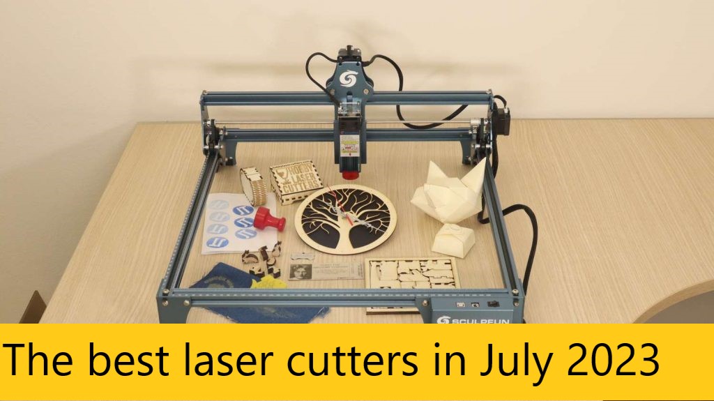
The best laser cutters in July 2023 – Cut, score and engrave a variety of materials, using the best laser cutters for ultimate precision. Our expert tester picks the top laser machine for home and studio use.

The best laser cutters are both increasingly capable and increasingly affordable. And so you don’t have to be a big business or professional manufacturer to use them: hobbyist and small business owners are finding they can greatly enhance their productivity and creativity too. (With Prime Day coming up, expect some of the brand’s below to drop in price, as well as good deals on the best laser engravers and the best laser cutter for a small business.)

The best laser cutters can be used to cut materials, of course, but also engrave and score. Working with digital drawing software, you can transfer the most meticulous designs to a material of your choice. Most of the best laser cutters now come with bespoke apps too and can be used on desktop, tablet or mobile. Laser cutters are becoming more accessible and match up to the best Cricut alternatives and Cricut machines for modern digital crafting.

But which model should you buy? With so many options on the market, it can be challenging to choose the right one for your specific needs. In this article, I bring together the best laser cutters available today, considering factors such as cutting power, precision, software compatibility, and ease of use. I’ve personally tested many of the laser cutters below.

The best laser cutters: my quick picks

Why you can trust Creative Bloq  Our expert reviewers spend hours testing and comparing products and services so you can choose the best for you. Find out more about how we test.

The best laser cutters available now

01. xTool P2

The best laser cutter for flexibility

SPECIFICATIONS

Materials: Wood, acrylic, aluminium, leather and more
Engraving/cutting area: 600 x 308 mm
Power: 55W CO2 laser

REASONS TO BUY

+

Powerful and fast laser

+

Expandable workspace

+

Can do everything you need

REASONS TO AVOID

Spend extra to get more from the P2

The xTool P2 is the newest laser cutter from a brand that is fast becoming one of the more popular in this space, with a laser engraver and cutting machine for most uses. The headline news is the P2 is a 55 watt CO2 laser cutter, just pipping Glowforge and comparable to the Gweike Could Pro. (Read my xTool P2 explainer for a detailed breakdown of this laser machine.)

It is simple to the Glowforge Pro below, so this is a metal casing with a glass lid and inbuilt extractor fan. It’s designed to be clean and easy to use. The P2 boasts some impressive stats too, its workspace is larger than Glowforge Pro; P2 is 600mm by 308mm, while Glowforge Pro is 495mm by 279 mm. Though, to be clear, Glowforge Pro has a passthrough that works out of the box while P2 requires an add-on, the Automatic Conveyor Feeder to really make use of its expandable size (3,000 x 500 mm).

Read More : Mavericksystemscorp.com

The best laser cutters in July 2023

What could be seen as P2’s weakness is actually one of this laser cutter’s strengths. xTool has a history of offering interesting add-ons, and the P2 is no different. You can increase the size of the workspace height using a Riser Base. The P2 is speedy too, running at 600 mm/s, it cuts 18mm basswood in one pass with ease.

The xTool P2 is cheaper than the Glowforge Pro (below) but quite comparable overall, despite having a slightly more powerful laser. One thing of note, P2 has a precision of 0.3mm while Glowforge has a macro camera that can reach 0.1mm levels. I have both laser cutters and am currently testing P2, and can say both machines are excellent. With P2 the advantage is it fits into xTool’s wider ecosystem of add-ons, ensuring that overall, this laser cutter can do pretty much anything, including rotary engraving (purchased separately).

02. Glowforge Pro

The best laser cutter for small studios

SPECIFICATIONS

Materials: Various
Engraving/cutting area: 27.9 x 49.5 cm
Power: 45W

REASONS TO BUY

+

Fast laser cutter and engraver

+

Supports many material types

+

Effortless to use and good app

REASONS TO AVOID

Ideally needs the Air Filter accessory

Glowforge Pro does for laser cutters what Cricut has done for craft cutters; this is a beautifully designed ‘laser printer’ that removes the mess and fuss and packages it all in a clean and approachable device, making it easily the best laser cutter around at the moment (for a price). This model is the top Glowforge laser cutter, while the brand has a the medium Plus edition and a slightly less powerful Basic model.

The Glowforge does the same cutting and engraving as many of the best laser cutters on my list, but its design keeps any mess inside the machine (a filter sucks away any dust and debris into an external air filter). Designs are sent to the machine via a bespoke app, and the Glowforge machines support Windows, Mac and tablet devices.

The Glowforge Pro uses a high-spec Class 4, 45 watt laser which is the most powerful you can get outside of an industrial use. (The Plus and Basic use a 40 watt, Class 1 laser, which is still more powerful than most on this list.) In my Glowforge Pro review this laser cutter impressed with its speed, ease of use and an excellent design app. It does, however, ideally need to be used with the Glowforge Air Filter accessory.

It’s this ease of use and clean approach to laser cutting and engraving that ensures the Glowforge makes it to No.1 on my list. It looks like a standard printer but can engrave everything from metal to wood and tiles to paper and leather – it’s perfectly suited to every task that requires accurate cutting too, from costume creation to model work. This Pro model comes with a ‘passthrough’ slot for large lengths of material, making it an ideal wood laser cutter – you can even make furniture. The results are always great, making this the best laser cutter for small business overall.

Types of Heavy Construction Equipment and Their Uses

Types of Heavy Construction Equipment and Their Uses

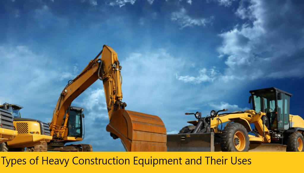
Types of Heavy Construction Equipment and Their Uses – In 2018, people bought more construction equipment than ever, thanks to a growing number of commercial, residential, and industrial projects that require heavy-duty tools and machinery to get the job done. Whether you’re working hard at a construction site, conducting road maintenance on a busy highway, or searching for the right tool for your large-scale landscaping project, there is a piece of equipment out there to make the work both easier and safer.

In this guide, we’ll discuss some of the most common types of heavy equipment and their applications.

1. Articulated Trucks

Articulated trucks are a type of heavy-duty dump truck that many praise for their versatility and adaptability. Unlike rigid haulers, articulated trucks consist of both a cab and a narrow trailer, or dump box. The two connect via a pivoting hinge. They are ideal for applications on challenging worksites with little to no paved roads, steep slopes, slippery or sandy surfaces, or low ceiling height.

You’ll find these at many types of job sites, including:

  • Mining
  • Recycling and scrapping
  • Material and aggregate hauling
  • Utility construction

Always match an articulated truck rental or investment to the size and type of load it will be hauling.

2. Asphalt Pavers

Asphalt pavers are usually accompanied by dump trucks carrying asphalt, which moves the material into the paver. Once it’s full, the asphalt paver uses dispersion augers to disperse the asphalt across a leveled surface. Then, it rolls it flat with a hydraulic cylinder, creating a solid, stable place to drive or walk.

You can use these pavers to lay asphalt on places such as:

  • Public and private roads
  • Driveways
  • Parking lots
  • Bridge decks
  • Recreation courts
  • Industrial sites
  • Building construction

Asphalt pavers are available in a variety of paving widths and speeds.

3. Backhoe Loaders

A backhoe loader is a single piece of equipment that can function as either a backhoe, a tractor, or a loader. The durable backhoe is located on the back of the machine, while the loading mechanism is in the front. The central operating machine is the tractor.

Because it’s capable of handling so many different jobs, you can use a backhoe loader for things like:

  • Farming
  • Excavation
  • Construction
  • Hauling
  • Digging

4. Boom Lifts

Boom lifts are a type of aerial lift mechanism. You might have also heard of it referred to as a basket crane or cherry picker. These attachments allow workers to reach elevated work areas but are not limited to only industrial or construction projects.

They are versatile and used across a variety of industries, including:

  • Forestry
  • Construction
  • Painting
  • Farming or harvesting
  • Window cleaning
  • Fire fighting

There are several different types of boom lifts, including telescoping and articulating. Boom lifts are suitable for one or more workers at a time, depending on the size of the bucket or platform.

5. Cold Planers

Cold planers are a type of heavy equipment for construction that utilize rotating drums and carbide cutters to mill pavement or asphalt. You can use a cold planer for either minimal or in-depth removal. Because pavement and asphalt milling creates a lot of dust, most cold planers utilize a water system to maintain a clean and safe work environment.

There are many reasons why one might use a cold planer to mill a roadway, such as:

  • Recycling asphalt for new roads or other projects.
  • Creating rumble strips for use along highways.
  • Repairing existing damage.
  • Smoothing land before paving to minimize any future potholes or cracks.

Read More : Mavericksystemscorp.com

Types of Heavy Construction Equipment and Their Uses

Like most heavy-duty equipment, cold planers are available in various sizes to suit several types of projects. Smaller machines are easily navigable and suitable for minor milling projects, while large machines are more challenging to navigate but can tackle large-scale projects with ease.

6. Compactors

Plate compactors use a heavy, vertically vibrating plate to crush and compact a surface into a level, flat area. The force behind the plate and the quick and repetitive movements work to break down and compact debris. In addition to industrial applications, you can also use a plate compactor to flatten an expanse of soil, sand, or gravel.

Depending on your application, choose between a single, reversible, or heavy-duty plate compactor:

  • Single plate: Single plate compactors are suitable for small-scale asphalt or building projects, like home renovations or laying sidewalks and driveways.
  • Reversible plate: For projects that require more versatility, reversible plates operate in multiple directions.
  • Heavy-duty plate: Heavy-duty plate compactors are the best option for large-scale industrial, construction, or roadway projects.

7. Compact Track and Multi Terrain Loaders

You can use both a compact track loader and a multi-terrain loader to transport heavy worksite materials. The two machines look and function similarly, but they are not the same. Compact track loaders are intended for more rugged, heavy-duty use than a multi-terrain loader. However, that’s not to say a multi-terrain loader isn’t powerful or effective — it’s just better suited for terrains that require more care, like sod or turf, while the compact track loader can handle more challenging surfaces like rocks, mud, and sand.

While each offers an unparalleled level of versatility and traction, you must consider job site conditions when choosing a piece of loader equipment.

8. Dozers

Bulldozers, also known as track-type tractors and crawlers, are critical pieces of machinery for several types of projects, including:

  • Farming
  • Land clearing
  • Road construction
  • Demolition
  • Home renovation

Dozers use a heavy-duty track to move with blades that can push rocks, building materials, debris, sand, snow, or dirt. There are a few different types of dozer blades, including the flat, edgeless straight blade, curved universal blade, and semi-universal combination blade.

9. Draglines

Draglines are a type of large-scale excavator used for reaching extensive depths at surface mining sites, above ground excavation sites, and more. Draglines function using a tall boom arm equipped with wire-based drag and hoist ropes. These ropes work together to move an attached bucket to and from its point of application. Once in place, the dragline operator controls the bucket so it can collect and move debris by dragging it across the surface.

Because they are so tall and heavy, many draglines are assembled on the worksite rather than transported, though there are smaller models available.

10. Drills

Rotary blasthole drills are a type of heavy equipment used for drilling holes at mine sites. Autonomous drills are a growing trend among equipment handlers because they have built-in features that can help you complete projects quickly and safely.

For example, automated drills today might feature:

  • Depth tracking
  • Built-in cameras
  • Automatic leveling, retracting, and drilling
  • HVAC systems to cool while limiting dust exposure

Non-automated drills offer just as much power, but these features can enhance the comfort and safety of your works as well as the overall productivity of the equipment.

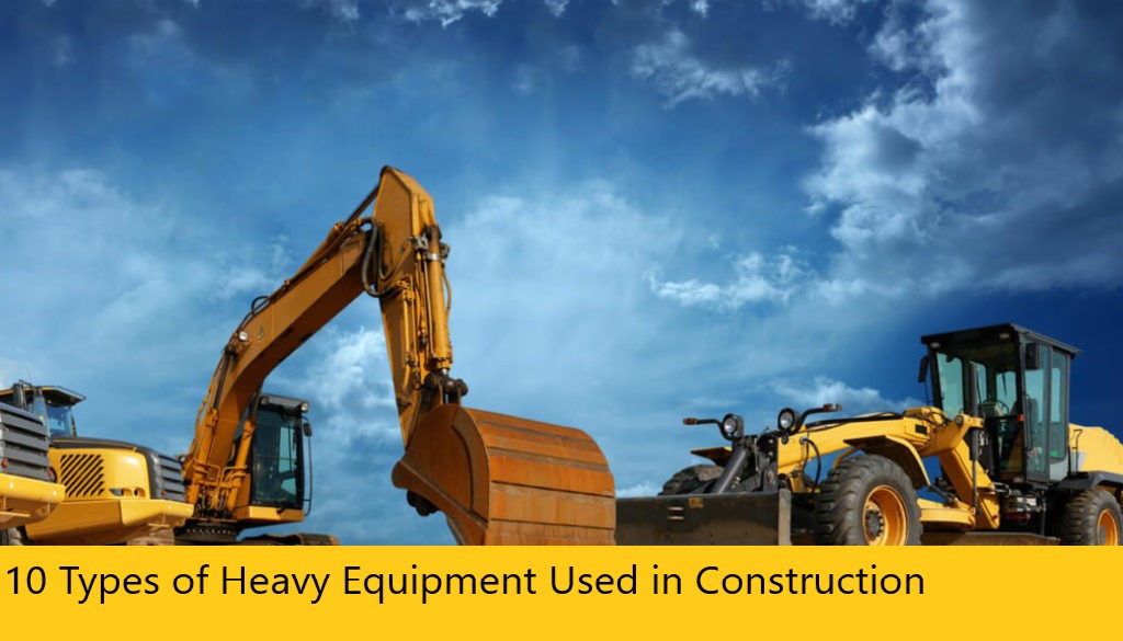
10 Types of Heavy Equipment Used in Construction

10 Types of Heavy Equipment Used in Construction

10 Types of Heavy Equipment Used in Construction – Heavy construction equipment are used for various purposes in large projects. Selection of different types of heavy equipment depends on the size of the work and economy of the project. These make construction process easier and faster.

Types of Heavy Construction Equipment

Different types of heavy equipment commonly used in the construction are as follows:

  1. Excavators
  2. Backhoe
  3. Dragline Excavator
  4. Bulldozers
  5. Graders
  6. Wheel Tractor Scraper
  7. Trenchers
  8. Loaders
  9. Tower Cranes
  10. Pavers
  11. Compactors
  12. Telehandlers
  13. Feller Bunchers
  14. Dump Trucks
  15. Pile Boring Machine
  16. Pile Driving Machine

1. Excavators

Excavators are important and widely used equipment in construction industry. Their general purpose is to excavation but other than that they are also used for many purposes like heavy lifting, demolition, river dredging, cutting of trees etc. Excavators contains a long arm and a cabinet. At the end of long arm digging bucket is provided and cabinet is the place provided for machine operator. This whole cabin arrangement can be rotatable up to 360o which eases the operation. Excavators are available in both wheeled and tracked forms of vehicles.

2. Backhoe

Backhoe is another widely used equipment which is suitable for multiple purposes. The name itself telling that the hoe arrangement is provided on the back side of vehicle while loading bucket is provided in the front. This is well useful for excavating trenches below the machine level and using front bucket loading, unloading and lifting of materials can be done.

3. Dragline Excavator

Dragline excavator is another heavy equipment used in construction which is generally used for larger depth excavations. It consists a long length boom and digging bucket is suspended from the top of the boom using cable. For the construction of ports, for excavations under water, sediment removal in water bodies etc. can be done by dragline excavator.

4. Bulldozers

Bulldozers are another type of soil excavating equipment which are used to remove the topsoil layer up to particular depth. The removal of soil is done by the sharp edged wide metal plate provided at its front. This plate can be lowered and raised using hydraulic pistons. These are widely used for the removal of weak soil or rock strata, lifting of soil etc.

Read More : Mavericksystemscorp.com

10 Types of Heavy Equipment Used in Construction

5. Graders

Graders also called as motor graders are another type of equipment used in construction especially for the construction of roads. It is mainly used to level the soil surface. It contains a horizontal blade in between front and rear wheels and this blade is lowered in to the ground while working. Operating cabin is provided on the top of rear axle arrangement. Motor Graders are also used to remove snow or dirt from the roads, to flatten the surface of soil before laying asphalt layer, to remove unnecessary soil layer from the ground etc.

6. Wheel Tractor Scrapers

Wheel Tractor Scrapers are earth moving equipment used to provide flatten soil surface through scrapping. Front part contains wheeled tractor vehicle and rear part contain a scrapping arrangement such as horizontal front blade, conveyor belt and soil collecting hopper. When the front blade is lowered onto the ground and vehicle is moved, the blade starts digging the soil above the blade level and the soil excavated is collected in hopper through conveyor belt. When the hopper is full, the rear part is raised from the ground and hopper is unloaded at soil dump yard.

7. Trenchers

Trenchers or Trenching machines are used to excavate trenches in soil. These trenches are generally used for pipeline laying, cable laying, drainage purposes etc. Trenching machines are available in two types namely chain trenchers and wheeled trenchers. Chain trenchers contains a fixed long arm around which digging chain is provided. Wheeled trenchers contains a metal wheel with digging tooth around it. To excavate hard soil layers, wheeled trenchers are more suitable. Both types of trenchers are available in tracked as well as wheeled vehicle forms.

8. Loaders

Loaders are used in construction site to load the material onto dumpers, trucks etc. The materials may be excavated soil, demolition waste, raw materials, etc. A loader contain large sized bucket at its front with shorter moving arm. Loader may be either tracked or wheeled. Wheeled loaders are widely used in sites while tracked or crawled loaders are used in sites where wheeled vehicles cannot reach.

9. Tower Cranes

Tower cranes are fixed cranes which are used for hoisting purposes in construction of tall structures. Heavy materials like pre-stressed concrete blocks, steel trusses, frames etc. can be easily lifted to required height using this type of equipment. They consists mast which is the vertical supporting tower, Jib which is operating arm of crane, counter jib which is the other arm carries counter weight on rear side of crane and an operator cabin from which the crane can be operated.

10. Paver

Paver or Asphalt paver is pavement laying equipment which is used in road construction. Paver contains a feeding bucket in which asphalt is continuously loaded by the dump truck and paver distributes the asphalt evenly on the road surface with slight compaction. However a roller is required after laying asphalt layer for perfect compaction.

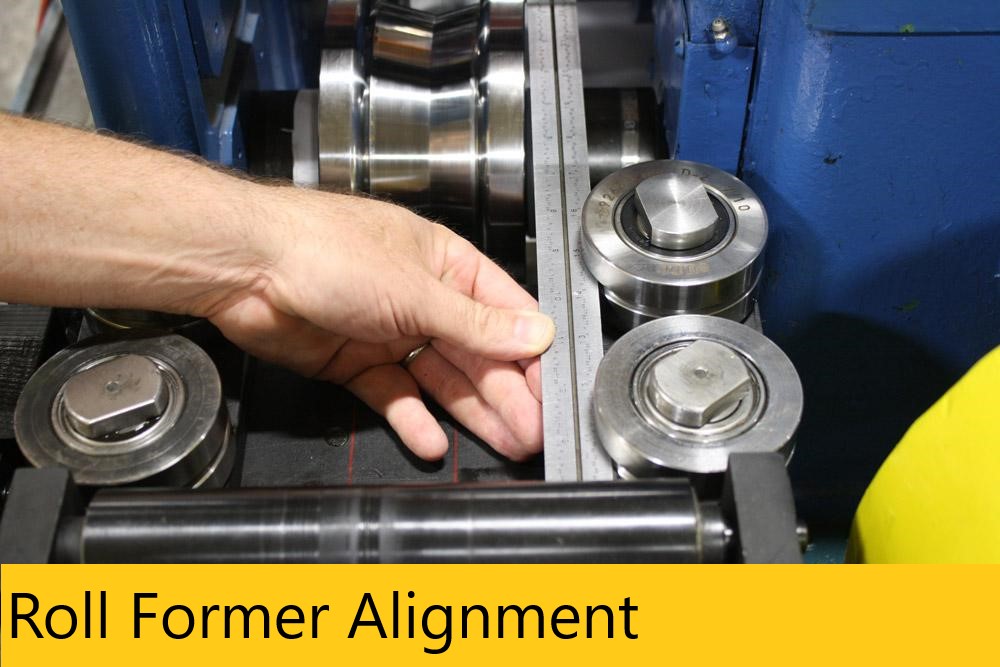
Roll Former Alignment

Roll Former Alignment

Are you experiencing difficulties holding tolerances in length or material straightness of your roll formed product? How about an angular or dimensional cross-sectional problem?

Roll Former Alignment – Roll Former misalignments can be very hard to find. Immediately everyone wants to start by moving the
guides, forming roll spacers or adjusting pressures. The proper way to determine where the problems are originating from is to start with a complete footprint of the entire line, from uncoiler to finished product. Every component should be set to a centerline or an offset centerline, then each component needs to be square, parallel, and perpendicular to each other, as well as centered.  If the mill has a two piece base it also needs to be level and square.
If any of the components are out of square to one another or too far off centers, then it can apply pressure on the product while feeding. It also causes it to rise or warp from one component to the next, which may also be a little misaligned, and by the time it reaches the roll form mill it has pressures applied to it from two or more directions.
Maverick Systems technicians can perform a laser inspection of the entire line. Once the inspection is complete, you will have a footprint of any and all misalignments throughout the length of the roll former line. The footprint allows our technician to determine which components are creating the alignment issues and begin making adjustments to correct them.

Here are some of the problems you may be encountering with the finished product due to misalignment of the Roll Former Line.

Camber

Camber is the variation of a side edge from a straight line, the gradual deviation from straightness of the edge of sheet or coil stock caused during the slitting operation. Camber is the edgewise curvature, a lateral departure of a side edge of sheet or strip metal from a straight line. Extreme camber contributes to curve, bow, and/or twist in the finished part.
Roll Former Alignment

Bow

Bow is the variation from a straight line in the vertical plane of a roll formed piece. It can be either cross bow or longitudinal bow.

Curve (also referred to as Sweep)

Curve is the variation from a straight line in the horizontal plane measured after the part has been roll formed. Causes of curve included incorrect horizontal roll alignment and uneven forming pressure. See bow, camber, sweep, and twist.

Twist

Twist is a term used to define parts when they resemble a corkscrew effect. This is often caused by excessive forming pressure in the final formed part. Twist should be less than 5° in 10 feet of roll formed parts. See bow, curve, camber, and sweep.

Another issue you may be experiencing is the length of leg size being different from one side

to the other or the size deteriorates as you go down the length of the part.

Leg

The leg is typically a 90% bend that is used for interconnection, mounting, or added structural support of the final product.

Length of the leg

A good rule of thumb is the leg length should be three times the thickness of the material.
Maverick Systems can provide a solution to all your alignment needs.

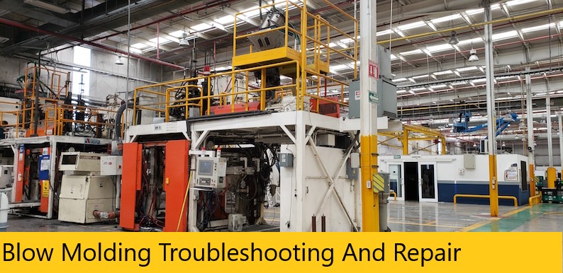
Blow Molding Troubleshooting And Repair

Blow Molding Troubleshooting And Repair

Blow Molding Troubleshooting And Repair – Maverick Systems offers emergency repair services, available twenty-four hours a day, seven days a week. Our field service engineers have extensive expertise in the repair and maintenance of your blow molding equipment. Our technicians have years of experience trouble-shooting and repairing all aspects of your blow molding operation, including filling, capping and auxiliary equipment used in your process.

comparison of optical systems and alignment lasers

The major players in the extruder alignment field today are optical systems and laser systems. The alignment of extruders has historically been dominated by optical systems. The technology goes back centuries, and while it can be useful, lasers, which are more accurate and user friendly are very quickly overtaking it. While the field has been dominated by optical systems, the drawbacks to the successful use of these products are illustrated in the following excerpts from THE HANDBOOK OF INTELLIGENT SENSORS FOR INDUSTRIAL AUTOMATION

The so-called standard for alignment has, in the past, been an optical system. For many years, optical tooling has been employed in the aerospace industry. To some extent, this same technology and the older technologies of older levels and straight edges have been used to align and make flat various types of machines. Optical systems fundamentally consist of a telescope. Inside the scope, at the focus of the eyepiece, is a cross hair that is projected into space, enabling the operator looking through at a target to note the position of the target relative to the cross hair. Frequently included with the instrument is a device called an optical micrometer, which causes the image to be displaced parallel to itself. In use, the operator rotates the micrometer to bring the center of the target onto the cross hair and reads the elevation of the change from the drum of the optical micrometer.

Read More :  Mavericksystemscorp.com

Blow Molding Troubleshooting And Repair

Optical devices include: engineering levels, tooling telescopes, theodolites, autocollimators, and other such devices. In all cases, the human eye is an essential part of the measurement system.

The human eye has a resolution capability of about 60 arc-seconds. This resolution is for a young, healthy eye looking at a target with 100-percent contrast under high light conditions. Age, poor sight, lower light levels, or lower levels of contrast will adversely affect this number and can double or triple it. The significance of the number is this: If you are looking through a 60-power telescope, the human eye will have a resolution of 1 arc-second or the equivalent of .006 inches in 100 feet. Typically, alignment telescopes, theodolites, and autocollimators use powers up to 40. This means that the typical optical instrument will have a resolution of about 1.5 arc-seconds under ideal conditions. This is equivalent to .009 inches at 100 feet. With lower contrast, poor light conditions, or imperfect eyesight, this number could easily reach .018 to .020 inches in 100 feet. In addition, there is a national specification requiring optical tooling telescopes and similar instruments to have a deviation of the cross hair, or a lateral shift of the cross hair of no more than .003 inches from close focus to infinity. The setup of optical systems requires a buck-in between the near and far targets to create a straight line. If all of these errors are added together, it is not possible to use an optical system to an accuracy of much better than .010 inches in 100 feet.

Contrast this with a laser system that may be used to an accuracy of .001 inches in 100 feet or proportionately smaller in shorter distances, and it is possible to begin to understand the significant improvement in accuracy provided by a laser alignment system.

Optics/Laser Comparison Test

Some years ago, the following test was performed with a major aircraft manufacturer. A target was placed 100 feet away and a direct comparison was made between an alignment laser and an optics telescope. In each case, the target was displaced and repositioned at the operator’s direction until the target was perfectly centered. The micrometer readings on the X – Y positioning stage were then read and recorded, and the operation was repeated. The same was done for both the optics telescope with a single operator and for the laser system. The tests were repeated for a number of operators.

The average error for the optics telescope was .010 inch, which coincides with the theory above. More importantly however, the difference between the average of one operator to another was as much as .040 inch, thus revealing the significant differences that can occur between human eyes.

By contrast, the alignment laser in the same circumstances had an average error of .001 inch, and the difference between the averages of the four operators was less than .0005 inch. This dramatically illustrates why laser alignment systems are so much more accurate than optical systems.

That’s the long story about optical vs. laser alignment. The short story is that optical alignment simply falls short in today’s world of high precision, tight tolerances, and ISO type demands.

Ta Grant, inc. To Provide National Sales Representation

Ta Grant, inc. To Provide National Sales Representation

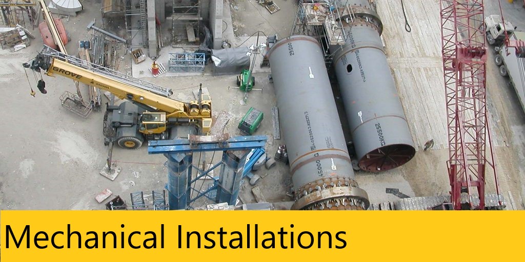
Mechanical Installations

Mechanical Installations

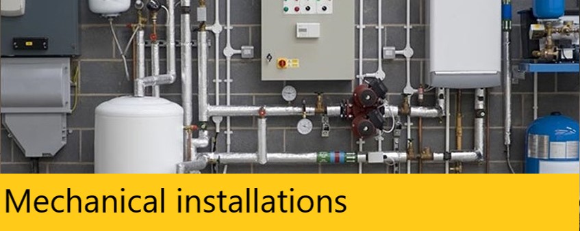
Mechanical installations

Mechanical installations

Mechanical installations – Maverick Systems provides mechanical construction and installation solutions for pneumatic conveying systems for the handling of dry bulk material, whether it be pellet, granule, powder or flakes. Maverick has experience with systems of all sizes, from single resin conveyor systems to large multi-station material handling system installations, plant re-locations, mezzanine & film tower fabrication, installation and laser alignment of equipment, custom machine base foundations ,Silo pads and silo installation.

We specialize in professional millright alignment and installation of process systems and machinery. Plastics Installation Services Include:

 INSTALLATION

  • Blown film towers
  • Resin silos (welded steel or bolted)
  • Material handling systems
  • Complete extrusion systems
  • Complete plant relocations
  • Tubing, hardware, auxiliary equipment
  • Pads & Foundations
  • Mezzanines

Mechanical installations

Read More : Mavericksystemscorp.com

ALIGNMENT SPECIALIST

  • Resin storage bins (steel or aluminum)
  • Blown film towers
  • Mezzanines
  • Cast film lines
  • Sheeting lines


LASER ALIGNMENT

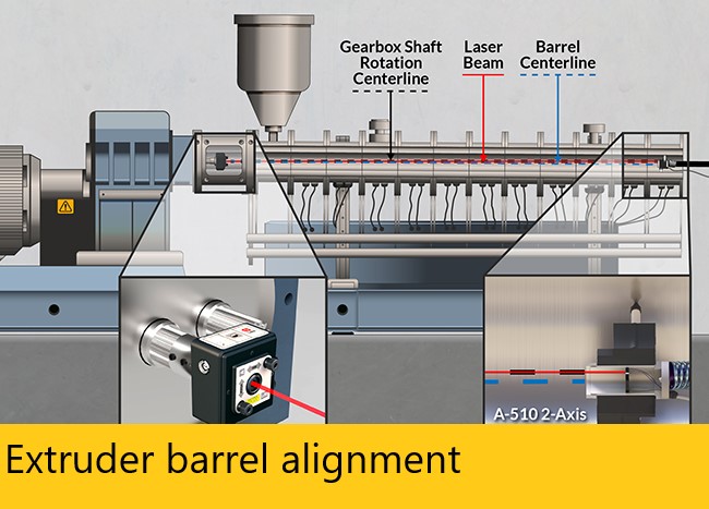
  • Extruder Barrel
  • IM Platen Alignment
  • Die to Nip Roll
  • Primary Nip Roll to Winder Parallelism
  • Motor Coupling

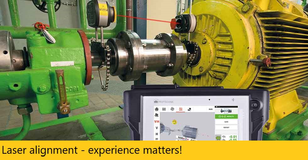
Laser alignment - experience matters!

Laser alignment – experience matters!

Laser alignment – experience matters! – Would you let someone perform laser surgery on your eyes without knowing how much experience he has on the equipment or whether the person using the laser is qualified?

The same applies to your machines. If you are expecting the best results possible, you need to know if the technician performing the alignments and accuracys on your equipment is factory trained and certified with the laser equipment they are using. Not only are our technicians fully trained and factory certified on the laser equipment, they all have a minimum of 8 years experience in the field.

Training and Experience – Team Qualifications

The laser technicians on staff at Maverick Systems Corporation have undergone extensive factory classroom training and certification through Hamar Laser, Inc. and Renishaw Laser. They are certified and experienced in all fields of machine geometry’s with the Hamar laser to ensure flatness, straightness, parallelism, perpendicularity of all axes, as well as extruder barrel alignment, injection molding platen alignment, spindle and bore alignment. With the Renishaw laser, they are trained and certified for linear positioning, repeatability, accuracy of movement, and are qualified to perform linear axis compensation in system controls to match the actual movement of the machines. They are fully trained on both the laser systems software and reporting systems so they can provide you with accurate and instant results on the machines alignment and accuracy.

Insist on more than just laser equipment knowledge

All of our laser technicians are also experienced millwrights in the machine tool and plastics industries, with up to 20 years of hands-on experience on a wide variety of machines. They know and understand the specifics of an extensive array of machines and can clearly communicate the factory requirements of your equipment and the steps necessary to correct misalignments.

Laser alignment - experience matters!

Read More : Mavericksystemscorp.com

They have an arsenal of laser equipment and software at their disposal to assist them in determining any problems or issues you may have with your machines. They work intimately with your technicians on each project to ensure that all misalignments or the issues causing the misalignments are corrected according to factory specifications or as close to tolerance as the machine’s condition will allow. They also work directly with our electronics and controls technician, if needed, to ensure that during the alignment process the machine is operated correctly and that the alignments are in strict adherence to the programming within the control. On new machine installations, the laser technician will also work directly with the control manufacturer representative on site.

Leadership and industry expertise

Maverick Systems Corporation’s Field Services division is led by one of the foremost laser and machine experts in the field with almost two decades of industry experience. Building on this leadership, with our commitment to training and innovation, we have assembled a professional, highly qualified team who has undergone extensive classroom training and certification in all facets of machine tool and manufacturing installation, maintenance and laser alignment.

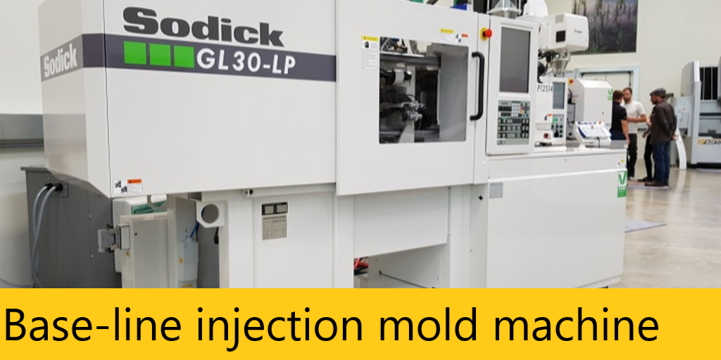
Base-line injection mold machine

Base-line injection mold machine

Several Factors Could Be the Issue

Base-line injection mold machine – Maverick Systems technicians are all factory trained and certified by Hamar Laser for Injection Molding Machines. All have hands on experience working with customers to provide them with alignment solutions on their injection molding machines. We have run into various obstacles along the way with foundation settling issues, level issues, platens not parallel to one another, molds not parallel to the platens, bent tie rods, injectors not aligning with molds and the list goes on.

Base-line your Injection Molding Machine

We recommend base lining your machine. While there may be only one issue with the machine there may also be several factors creating that problem. If you initially find the platens are not parallel to one another, stop there and try to find out why. Base lining the machine and doing a full inspection of level, flatness, squareness and parallelism of all the components may help you in your search.

When sufficient evidence is gathered, you should then correct all the issues to prevent similar mistakes in the future. On the bigger injection molding machines (1500 ton+), a series of data collecting needs to take place that requires more than one set up. Though it may require a full day to troubleshoot, afterward you will know the full geometries of the machine and where to start with corrections.

Read More : Mavericksystemscorp.com

Base-line injection mold machine

Reduce Downtime Changing Molds

Changing a mold is time consuming and realignment is a necessity. If a mold is slightly out of parallel to the platen, costly flashing and premature wear can occur. Inadequate alignment also results in excess wear on the injection-molding machine and can even lead to tie-bar breakage. With each tie bar costing at least $10,000, proper alignment is crucial. Maverick Systems can save you time and money with the mold changing process. Rather than using the traditional methods of alignment, we can “buck-in” to your platen plane and provide live alignment data. Misalignment errors can then be quickly adjusted using just one setup. Use of the Hamar laser L-723 speeds the alignment process significantly, and also reduces tooling and maintenance costs.

Reduce Stack Up Errors

One of the biggest complications with aligning machine tools using conventional methods is that many different alignment tools must be used, requiring a lot of time and increasing stack-up errors. Another concern is that an alignment is only as good as the tools used to perform it. The machinist master level is a good example: it has a resolution of .0005″ per foot, not very accurate for today’s ever-tightening tolerances.

The L-723 laser planes, by contrast, are flat to 1/2 an arc second (0.00003″/ft or 0.0025mm/M) in a 180° sweep and 1/4 arc second (0.000015″/ft or 0.001 mm/M) in 90° sweep. The laser planes are square to each other to within 1 arc second (0.00006″/ft or 0.005 mm/M). They further have the advantage of creating a single reference from which to measure machine geometry, significantly reducing stack-up errors.

Extruder barrel alignment

Extruder barrel alignment

The facts about Extruder Barrel Alignment or Bore Scoping

Extruder barrel alignment – Most extruding machines are built with the thrust bearings, shaft assembly, and the output shaft of the gearbox as one unit. The thrust shaft (which is splined, or keyed) holds and turns the screw, which is the centerline of the axis of rotation. If any of the components are not aligned from the centerline of the thrust shaft there will be friction between the barrel and screw or feed chamber and screw. Sometimes, both situations happen, depending on the amount of error off centerline. If there is friction between the barrel and screw, the amount of wear will increase causing either the barrel or screw (or both) to wear faster increasing your replacement costs dramatically.

The feed chamber is the next component. If the feed chamber screw guides are offset too far from the thrust shaft centerline, (feed chamber offsets are discussed in more detail in the offset section) it will put strain on the gearbox thrust shaft bearings, causing them to wear faster.

Next is the barrel input. Again, it’s important to know if there is an offset from the thrust shaft centerline either horizontally or vertically; it could cause the screw to rub at the input end of the barrel. More importantly, the offsets of the feed chamber need to be the same as the offsets at the barrel input. Offsets that differ would definitely create friction between the screw and the input end of the barrel. If offsets sound confusing, you can read more about them in the offset article.

Last is the barrel output. Most errors will be found from the centerline of the thrust shaft, and will usually be in both vertical and horizontal. Excess misalignment here will cause friction between the screw and barrel somewhere in the length of the barrel. Sag can also be an alignment issue in longer barrels.

Read More : Mavericksystemscorp.com

Extruder barrel alignment

Taking all of this into consideration, the following paragraph should make it more clear as to why the extruder components should be aligned to the centerline of the axis of rotation and why the thrust shaft is the logical choice for establishing the centerline.

Tolerances between the barrel and screw will average .008 total clearance, which is only .004 on all sides. The extruder is designed to shear, melt, and mix the plastic materials to give a good, uniform flow. If the output end of the barrel is out of alignment, then the screw is rubbing against the barrel at some point. At that contact point, there is minimal shearing and minimal mixing because there is no clearance at the rubbing point. However, there is a hot spot generated from frictional heat due to the screw rubbing against the barrel, causing the plastic material to melt hotter and faster. Now you have an area of material that is of different consistency. On the opposite side of the screw, there is also an area of material that is of different consistency. Because you have a wide gap of .008 that the plastic material is rolling over, not shearing, or mixing properly, the plastic material here will be cooler and harder. Now that you have plastic materials flowing at an uneven temperature, pulsating and surging has to take place. While it may be a very small amount, it could be serious enough that you can’t hold size.

The thrust shaft is what holds and turns the screw. If you have the feed chamber and the barrel aligned to the centerline of the thrust shaft, it will alleviate the friction areas in the barrel and allow the proper amounts and consistency for a uniform flow.

Maverick Systems can bore scope your extruder barrel using the latest laser technologies available. Giving you the most accurate barrel alignment possible.

Injection molding service and repair

Injection molding service and repair

Injection molding service and repair – Maverick Systems offers troubleshooting and repair of Injection Molding machines, including all equipment related to the molding process: Material handling, loaders, dryers, hot runner controls, robots and pickers, color mixing and material mixing equipment, cooling towers, pneumatic systems, hydraulic troubleshooting and repair, control issues, platen alignment, and tie bar inspection/replacement.

In addition we offer complete installation of injection molding equipment from arrival to production with a strong after installation commitment to the customer.

We strive to offer a complete maintenance and repair service no matter what brand of injection molding machine you own.

Maverick Systems technicians have over 30 years of experience in installation and maintenance of injection molding machines and we continue our training in the latest technologies to provide the highest quality of service to our customers. We work closely with manufacturers to ensure top quality repairs and stay within OEM specifications during an installation or retrofit. In addition to the newest machines on the market, we also service older models that are typically out of warranty and are no longer serviced by the OEM.

Are you experiencing any of these issues?

  • Slow recovery times
  • Having trouble with the hydraulics
  • Issues with the control
  • Process problems
  • Molds do not align properly
  • Platens aren’t parallel
  • PM program not satisfactory

Maverick Systems Corporation Services

  • Injection molding and extruder repair
  • Complete maintenance programs
  • Control repair and troubleshooting
  • PM programs
  • Repair to OEM specs
  • Material-handling systems
  • Retro fitting older machines
  • Peripheral equipment
  • Retrofit to customer specs
  • Hydraulic system troubleshooting
  • Extruder barrel laser alignment
  • Injection molding machine leveling
  • Motor coupling laser alignment
  • Platen parallelism alignment
  • Barrel wear inspection
  • Platen center alignment
  • Screw wear inspection
  • Tie bar inspection
  • Seized screw removal
  • Bent tie bar removal and installation

Read More : mavericksystemscorp.com

Injection molding service and repair

Auxiliary equipment including

  • Hot runner systems
  • Pneumatic control and supply
  • Material handling
  • Bed conveyor and overhead conveyor
  • Color mixing and material mixing
  • Dryer systems
  • Water-cooling systems
  • Barrel heater bands
  • Film lines
  • Blow form lines
Other services provided include turnkey installations, foundations engineered for your specific needs, grouting of machine bases, and isolator pads designed for injection mold machines and extruders.


Maverick Systems Corporation provides a complete solution to the plastics processing field. Located in Hurst, Texas 5-miles from DFW Airport. We provide local service to the Metroplex and surrounding areas as well as nationwide including Mexico and Canada.

Machine tool laser alignment and calibration

Machine tool laser alignment and calibration

Reduce scrap parts and protect your investment by having a quarterly or annual machine tool laser alignment. Machine tool alignment and calibration is required to maintain your ISO certification!


There is much more to maintenance than keeping the machine running!

Machine tool laser alignment and calibration – One of the most critical factors in any machine tool maintenance program is knowing your machine’s level of accuracy and tolerances. Your machine tool should be level, flat, and square in all axes, mechanically adjusted to acceptable tolerances, and any linear error should be corrected to OEM specifications – which includes documentation certifying the accuracy of the machine.


Significantly Reduce Part Setup Time

One benefit of having a properly aligned machine tool is that part setup time is significantly reduced. An article in the October 1998 issue of Quality in Manufacturing Magazine describes the incredible benefit of laser alignment to the John Deere Corporation. In the words of Jim Abitz, tool and die maker, “…[laser alignment] makes the operators a lot happier because they don’t have to struggle for two or three shifts to get a machine to work properly.”

Our Lasers Align 70% Faster Than Other Methods

Continuously sweeping lasers and live data output create a powerful combination to align machining centers up to 70% faster than traditional or interferometer methods. Downed machines will be up and running, producing quality parts in record time. Hamar’s continuously sweeping lasers are far superior to other point-and-shoot laser systems that require time-consuming manual laser rotation and target setup for each point measured. They also allow the use of multiple targets, which is especially helpful for large machine tools.


Simultaneously Measure 3 Axes with One Setup

Another great time saver is the laser’s ability to measure the three main axes of a machine at the same time. Not only can we measure the flatness and straightness of each axis, but we can also measure the squareness of the three axes. And if there are any additional axes, such as a rotary table or extending quill, we can easily check the parallelism to the main machine axes with the same setup!


How many of the statements below describe your machine? Do you know?

Machine

  • Circle interpolation perfect.
  • Part programs never edited.
  • Zero offsets in control.
  • Shims are never required.
  • Holds thickness tolerance.

Machine tool laser alignment and calibration

Read More : Mavericksystemscorp.com

Parts

  • Hole locations are exact.
  • Top and bottom parallel
  • All sides square.
  • Surface finish smooth
  • 180° center locations precise.
If three or more of the items above don’t describe your machine or the parts it produces then you probably have a misalignment or calibration issue. Machine tool alignment and calibration issues don’t go away, they get worse and create more problems and significant downtime. That’s why it’s critical to remove as many elements out of the equation as possible. Depending on the size and numbers of axes of the machine tool, the inspection and correction process for your geometrical errors and calibration of your linear axes may render your machine inoperable for a short time. However, once the initial corrections have been made, minor adjustments should be all that’s required if you have a scheduled inspection and correction performed annually.


Get an Annual Checkup

At Maverick Systems Corporation, we recommend performing a machine tool laser alignment and calibration check on an annual basis after the initial alignment has been performed. Afterwards, any problems that arise can be addressed immediately and corrected quickly.

The Machine Tool Alignment Process

During the course of a typical alignment and calibration session of a machine tool, it is not unusual to encounter some hidden problems. This is where our experience pays off. Having worked on a wide variety of machine tools, we can efficiently identify the problems and correct them as necessary.
Beginning with the machine base, we laser level and align it back to OEM specifications. Next, the ball screw is checked for endplay, and adjusted if needed. The gibs are then checked and adjusted back to specifications. Finally, we continue through all axes of the machine, ensuring the axes are square, parallel, and perpendicular to one another.
The geometry’s of the machine must be aligned before performing any linear calibrations as errors in geometry can effect the linear movement. After completion of alignment, we then proceed on with the linear error compensation of the axes in the control.

Return on Investment

Whether it’s one machine or an entire shop, Maverick Systems Corporation can set up your company with a scheduled laser alignment and calibration program that will fit your maintenance calendar. Your ROI will be immediate and your overall maintenance budget will go down.
It’s time to incorporate laser alignment and calibrations into your maintenance schedule.